
Pipe clamp: CAD-referenced patent line art
A split housing and fasteners are translated into a technical drawing. The result represents visible features from an image, not native CAD geometry or measured dimensions.
Use a CAD screenshot or render as a visual reference for a patent-style drawing draft. Upload a raster image, describe the product view you need, then inspect the PNG for details that require correction.
Free to try ·
Your patent drawing will appear here
Describe the view and components to generate a PNG for review.
A clear prompt helps direct the composition, while a human review checks the image against the invention.
Frame the complete part and choose an angle that exposes important holes and edges. Hide selection overlays that cover the model, and explain any occluded features in text.
Describe the housing split and visible fasteners. Upload a raster screenshot in the full workspace; this workflow does not read STEP files or recover parametric geometry.
Check geometry, numbering, and view consistency. PNG images do not contain editable CAD or vector layers, and filing requirements need a separate review.
Frame the complete part and choose an angle that exposes important holes and edges. Hide selection overlays that cover the model, and explain any occluded features in text.
Describe the housing split and visible fasteners. Upload a raster screenshot in the full workspace; this workflow does not read STEP files or recover parametric geometry.
Check geometry, numbering, and view consistency. PNG images do not contain editable CAD or vector layers, and filing requirements need a separate review.
Compare clamp line art, a CAD viewport reference and a bracket conversion. Visible holes, seams and ribs matter more than rendering materials.
A split housing and fasteners are translated into a technical drawing. The result represents visible features from an image, not native CAD geometry or measured dimensions.
A generic CAD viewport and model tree identify the clamp assembly. Select an angle that exposes housing divisions and fasteners before exporting a screenshot.
Both panels show the same L-shaped bracket, four mounting holes, and reinforcing rib. Count the holes and compare rib orientation before accepting the drawing.
Translate visible CAD features into line art · Export a useful screenshot from the CAD viewport · Check hole counts, edges, and reinforcement
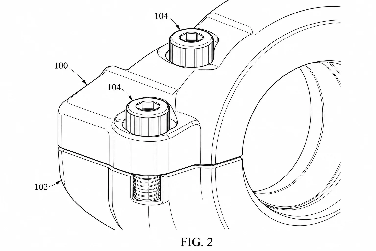
Describe the housing split and visible fasteners. Upload a raster screenshot in the full workspace; this workflow does not read STEP files or recover parametric geometry.
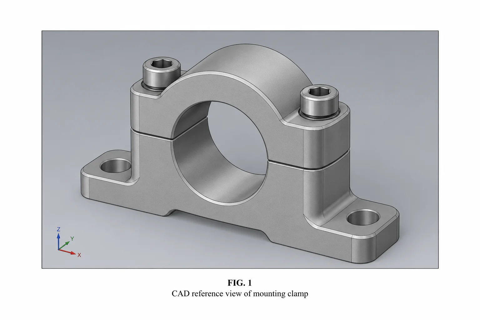
Frame the complete part and choose an angle that exposes important holes and edges. Hide selection overlays that cover the model, and explain any occluded features in text.
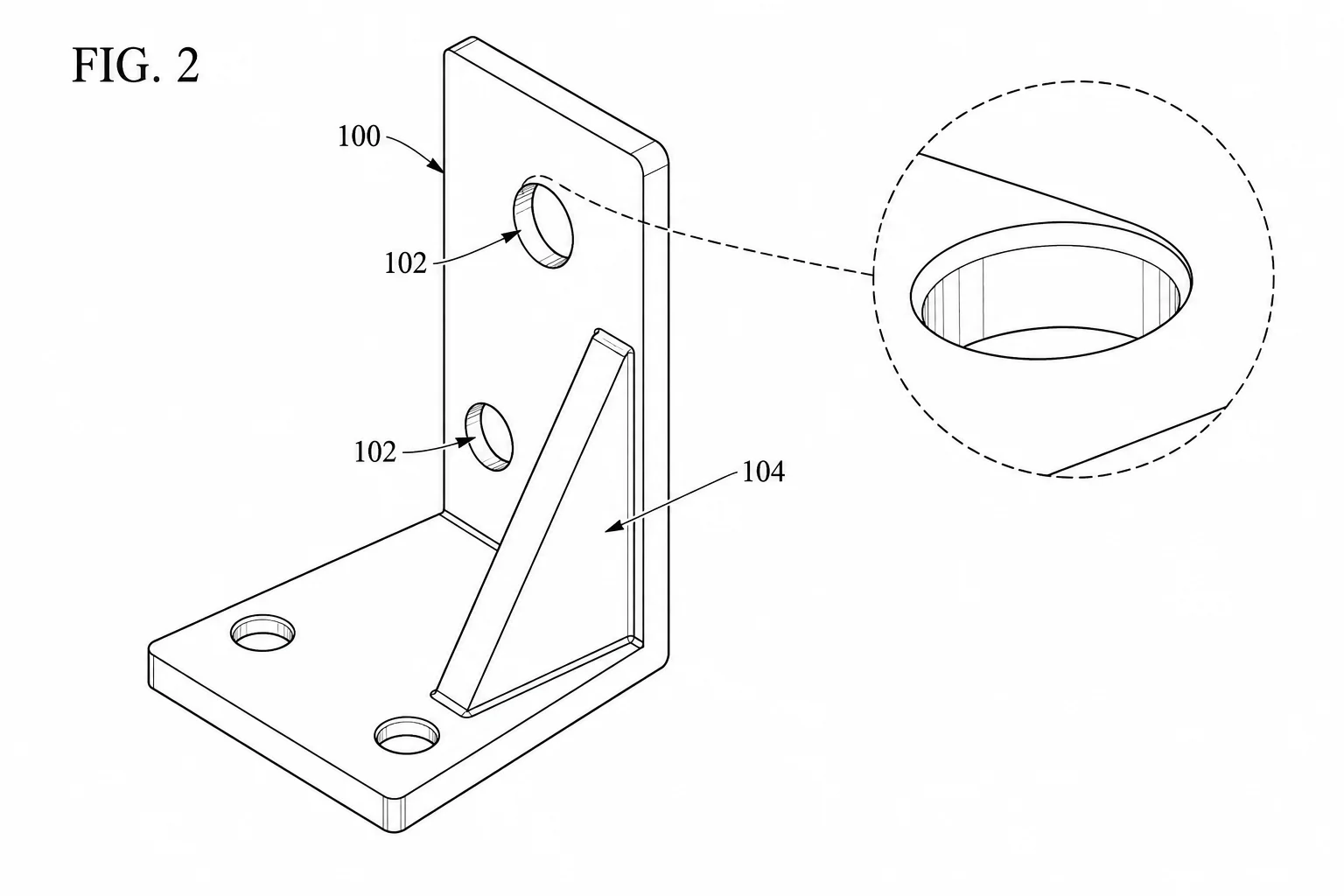
Count openings on the visible face before reviewing decorative line quality. This enlarged bracket detail shows two holes on the upright plate, a reinforcement rib and one hole rim. Trace each edge back to your CAD reference; the crop is a geometry check, not a measurement or a complete bracket view.
Compare subscription plans and one-time credit packs for AI patent drawing generation. Every generated image downloads as PNG and should be reviewed before use.
For occasional patent drawings.
Includes
For regular invention and product workflows.
Includes
For frequent, high-volume image generation.
Includes









 Patent drawing
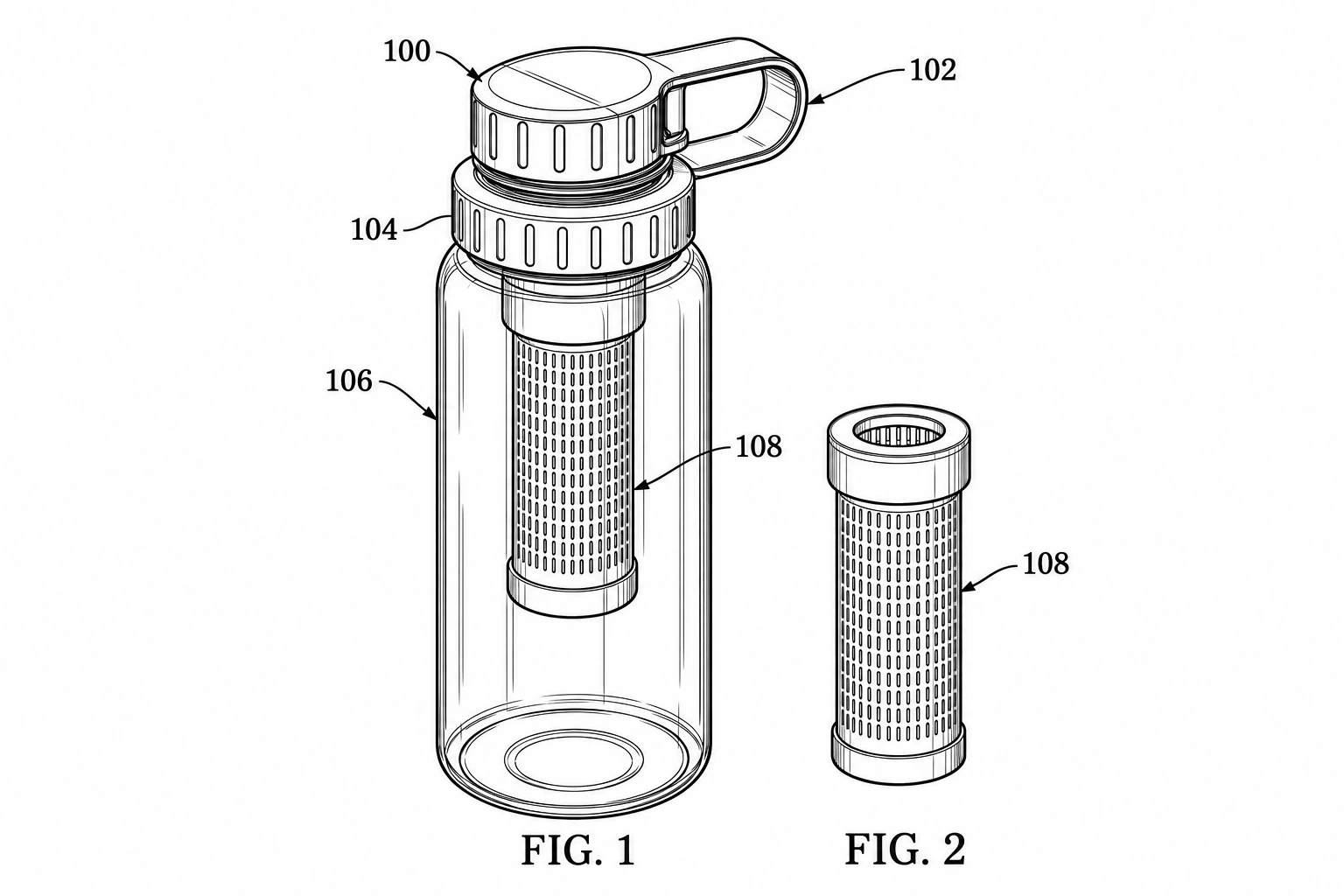
Generate a two-dimensional perspective patent-style line drawing of a physical product. The result is a flat PNG illustration, not a rotatable 3D model or CAD geometry file.
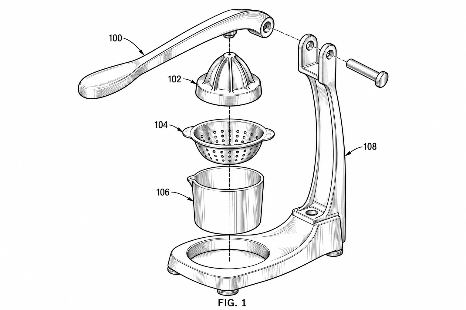 Patent drawing
Create an exploded-view composition that separates plausible components of a physical product. Describe how the parts fit together, then check the generated PNG for component order and alignment.
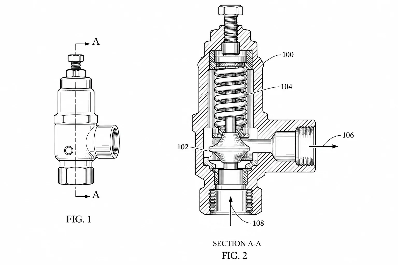 Patent drawing
Create cross-section patent drawings from text or a reference. Show internal parts, section boundaries and hatching, then review and download a PNG.